A phase-aware OpenFOAM study of how a rectangular-slot liquid–gas interface deforms under aerodynamic forcing across an early-time VOF window.
The contribution is a reproducible bridge from explicit CPU/MPI numerics to native-time phase fields, mixture-flow diagnostics, and topology and morphology measures across all 25 recorded states.
How does the interface respond after leaving a non-circular slot?
The calculation follows that response through native-time phase fields, mixture-flow diagnostics, cross-sections, and connected morphology while keeping the interpretation tied to the available early-time window.
Physical problem and nondimensional regime
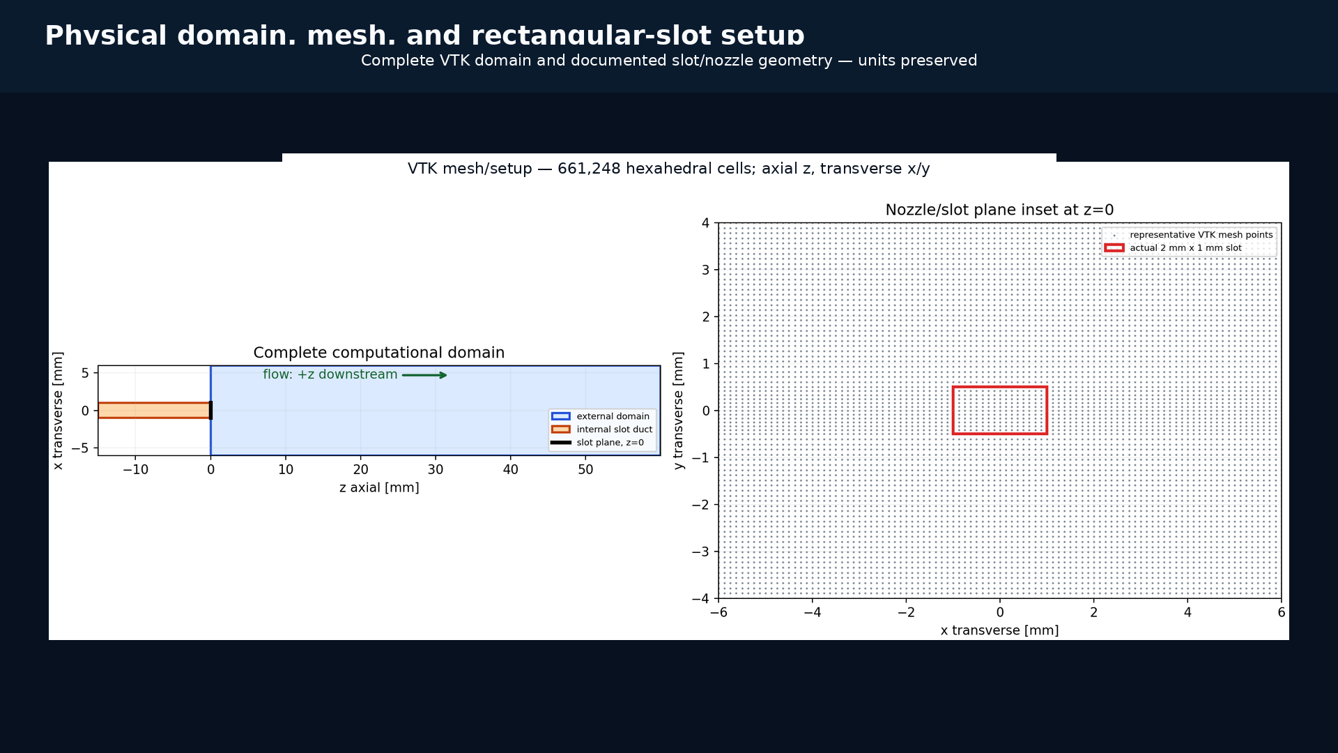
The scaled high-density-gas case uses a gas-density factor of 20, a 12 m/s liquid inlet speed, and an estimated gas-side Weber number We_g = 53.3333. These parameters increase interface forcing while keeping the interpretation tied to this numerical configuration.
Coordinate and phase convention
Flow proceeds in +z; x and yare transverse. alpha.water is liquid fraction, 1-alpha.water is its derived two-phase gas complement, and U is mixture velocity.
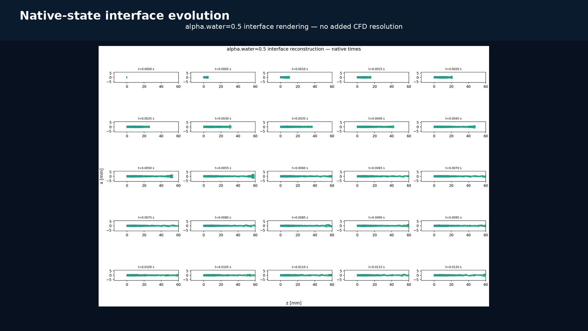
All 25 inventoried native alpha.water=0.5 states, presented as labeled discrete holds at 24 fps with no temporal geometry interpolation.View the full 25-state static figure
The same sequence as a full-resolution static figure, so time labels remain readable without video playback.
Phase and flow diagnostics
Phase semantics stay attached to every derived product.
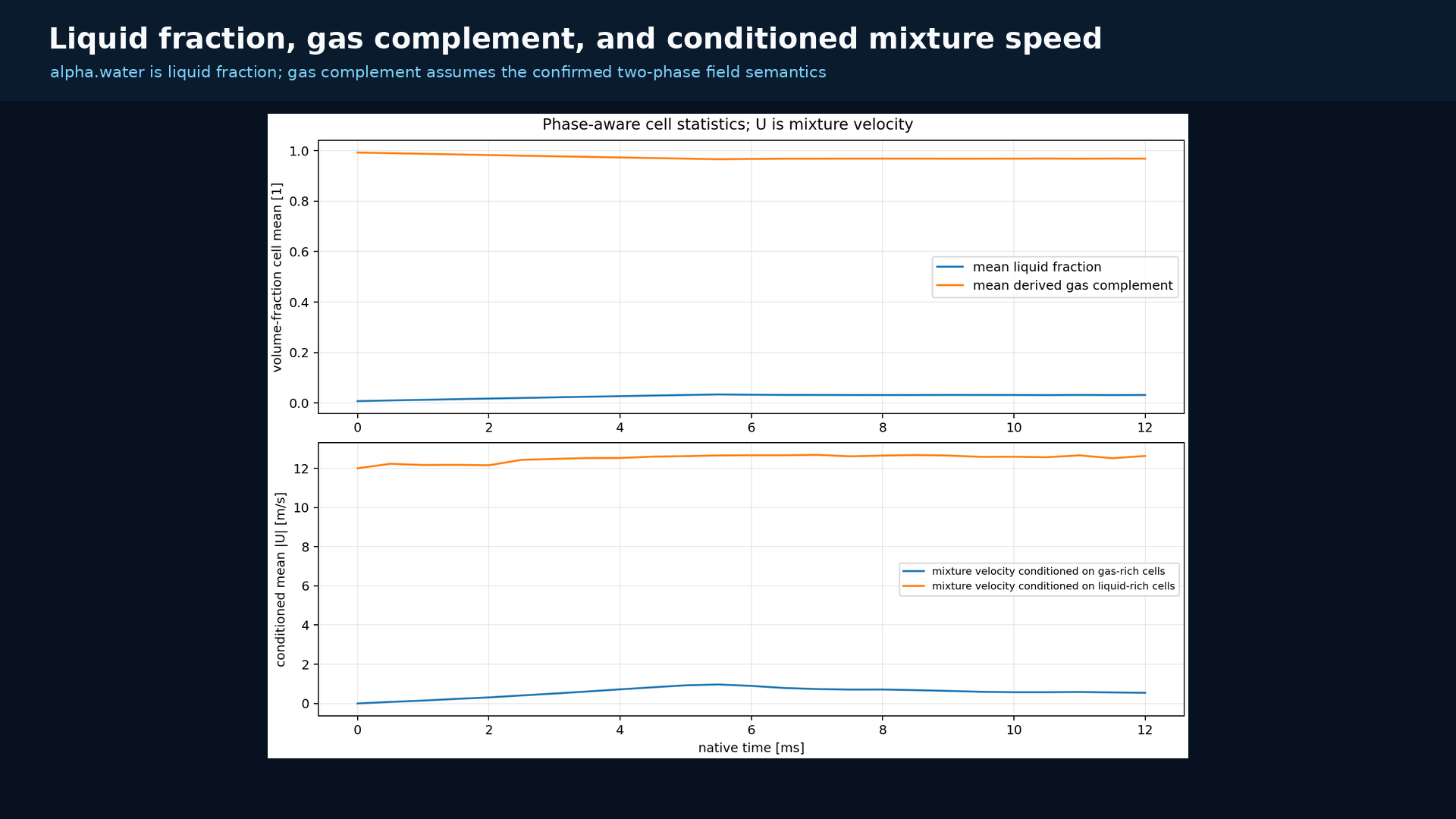
Liquid fraction, its derived gas complement, and mixture velocity are analyzed separately so each figure retains its field meaning, threshold, units, and native time.
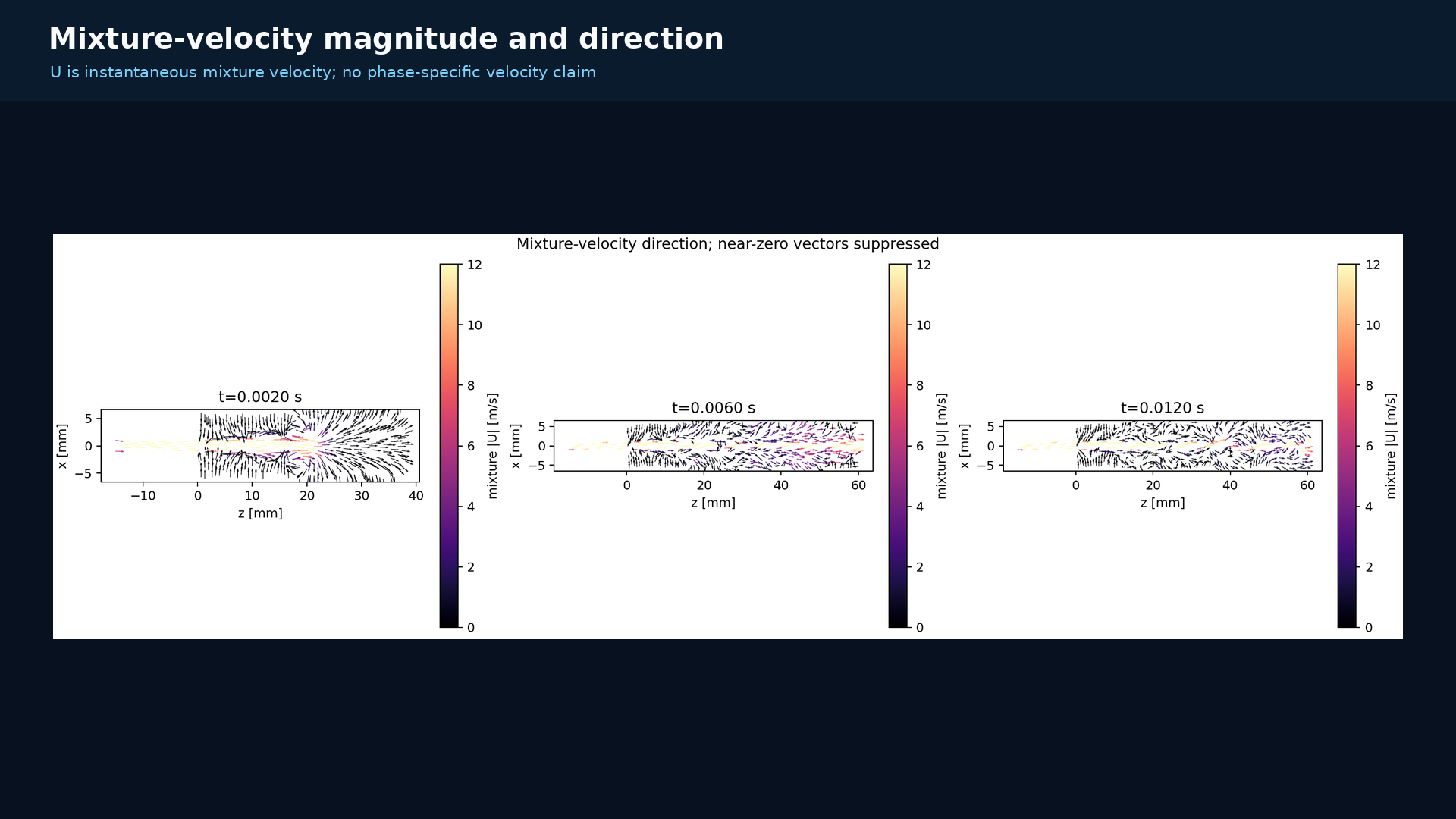
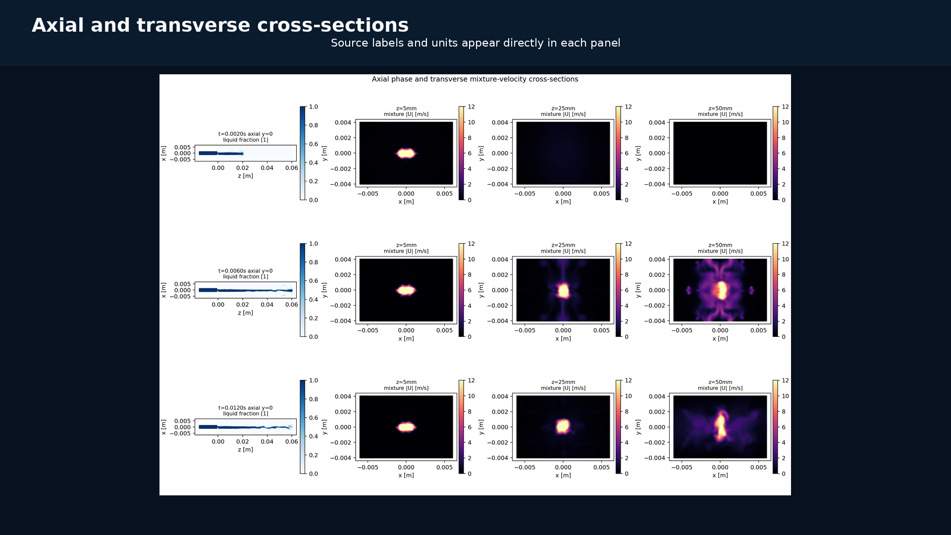
alpha.water is liquid fraction. The gas series is the derived complement; both conditioned speed series use mixture U.Magnitude and direction of instantaneous mixture U at 0.002, 0.006, and 0.012 s.
View the secondary field-gallery video
Controlled field gallery. Full-resolution figures below carry the labels needed for mobile and close reading.
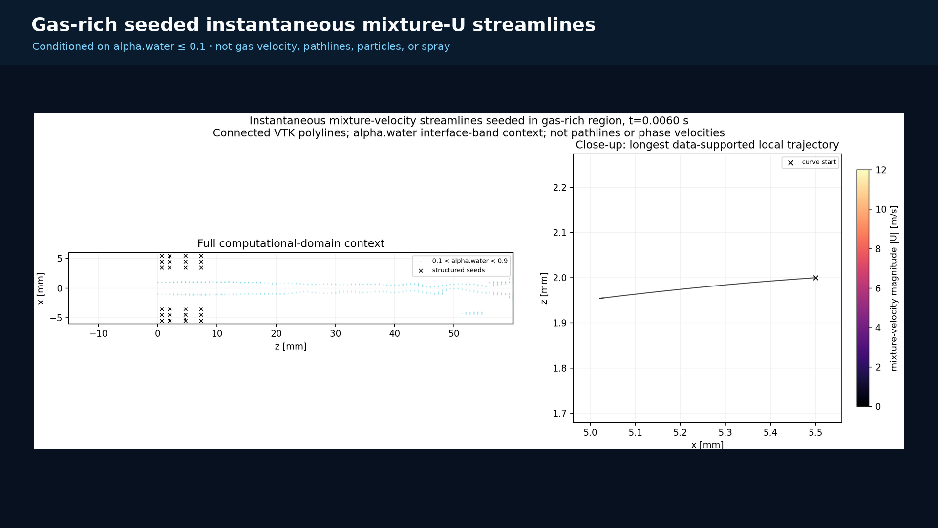
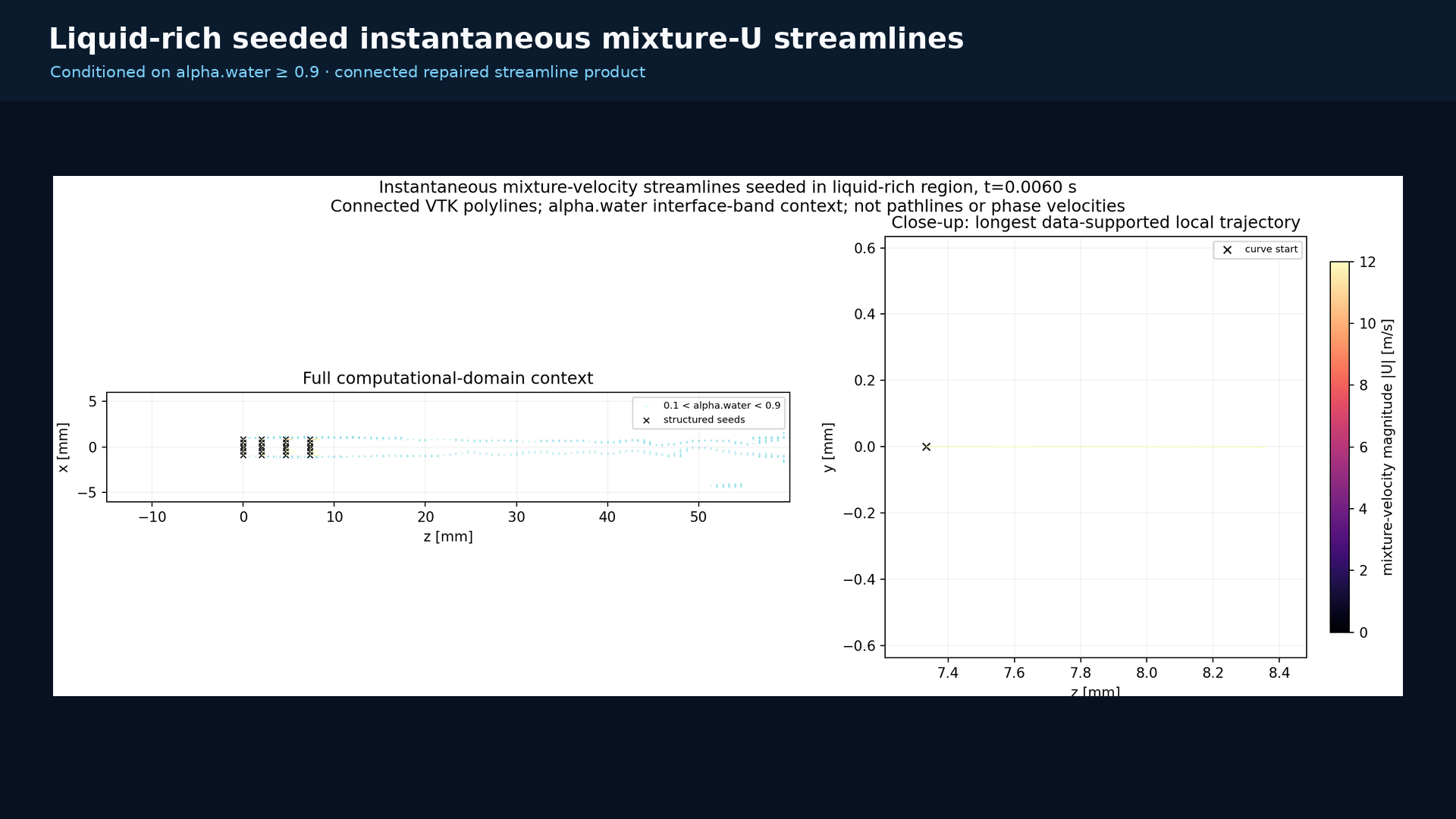
At the native 0.006 s state, connected curves are seeded deterministically in gas-rich (alpha.water ≤ 0.1) and liquid-rich (alpha.water ≥ 0.9) regions. They are instantaneous mixture-U curves conditioned on seed location.
Gas-rich seeding at 0.006 s: 24 connected mixture-U curves with full-domain and local views.Liquid-rich seeding at 0.006 s: 24 connected mixture-U curves with full-domain and local views.
Morphology and representative results
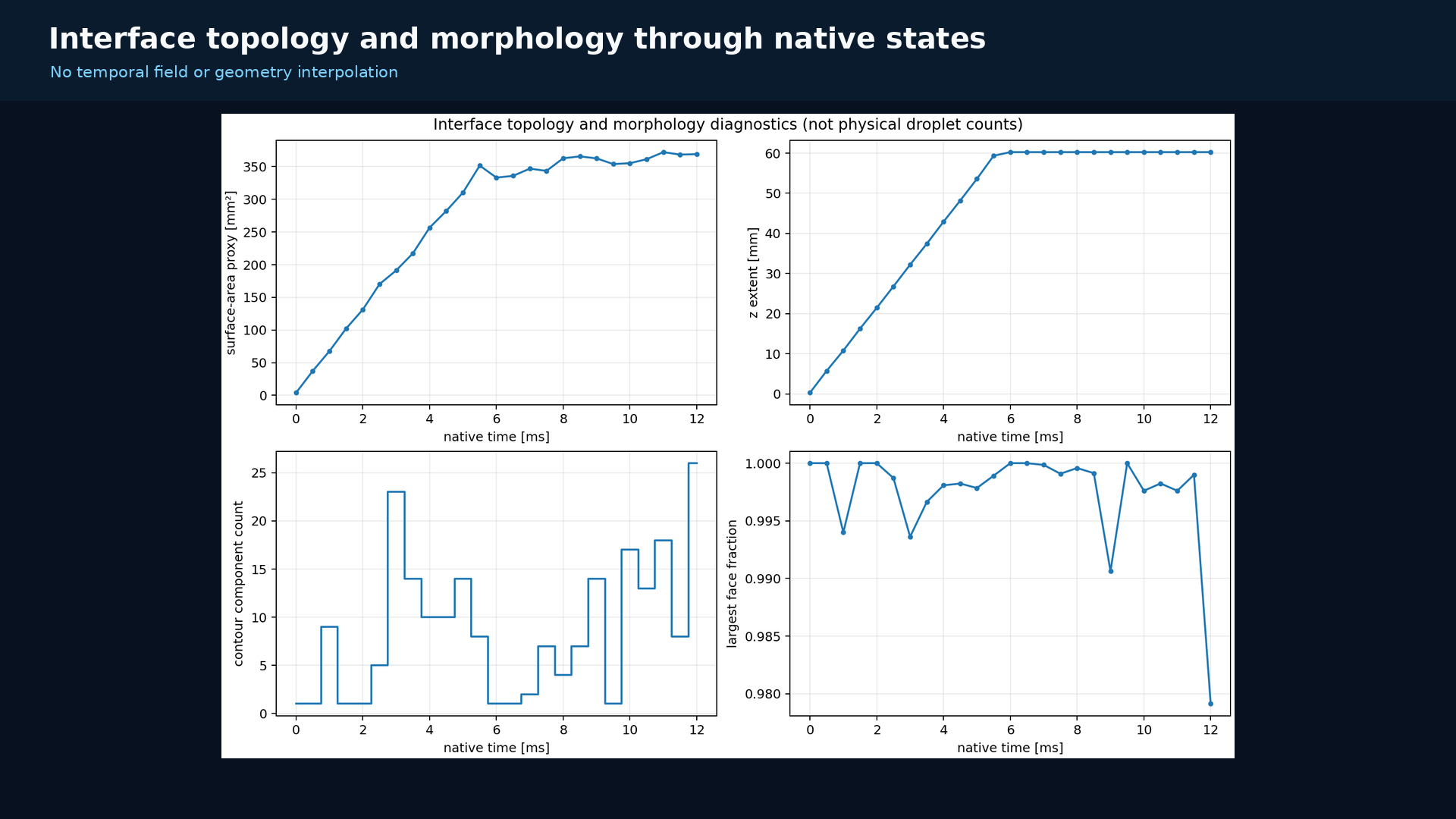
One connected interface remains dominant across the recorded window.
Surface metrics track area proxy, axial extent, component count, and largest-component dominance at every native state. The largest component retains a minimum face fraction of about 0.979 while the interface deforms over the early-time sequence.
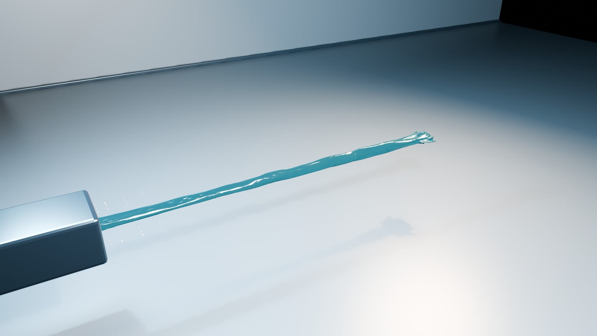
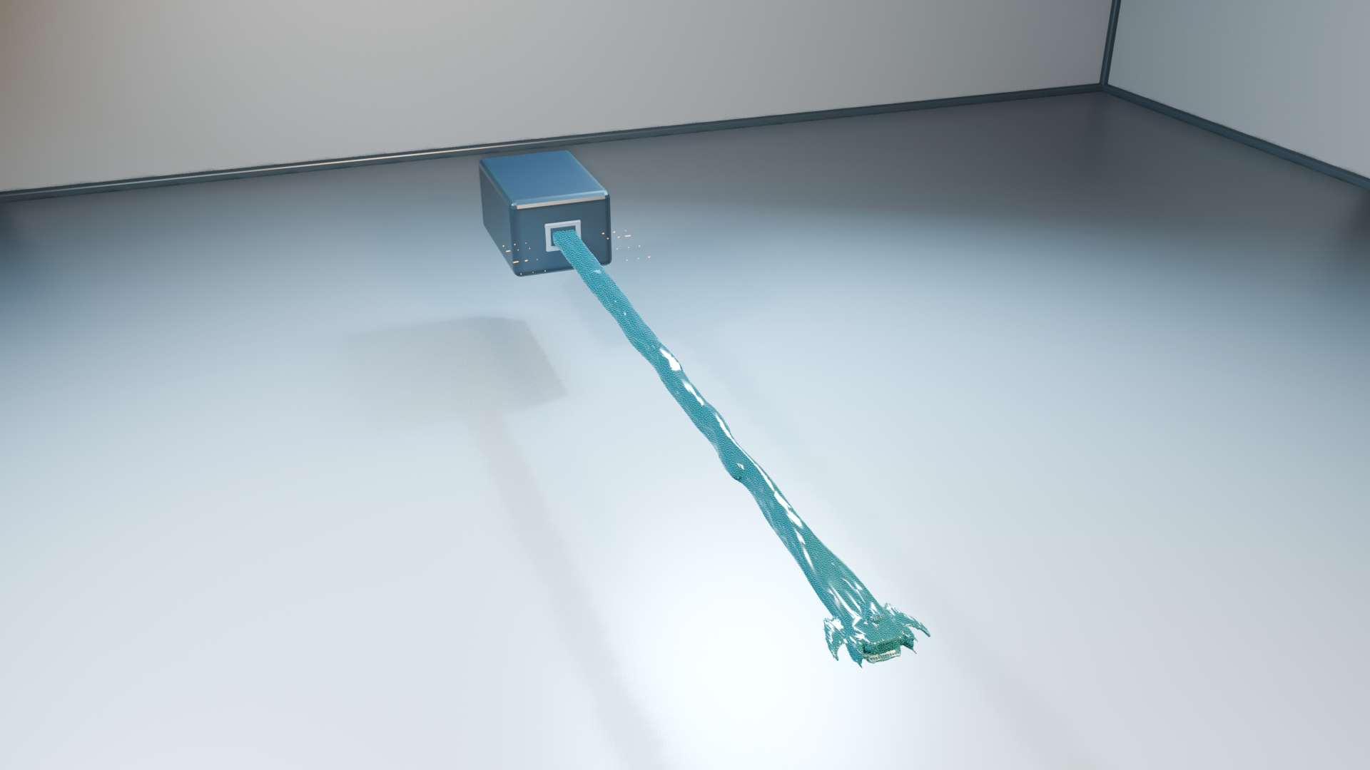
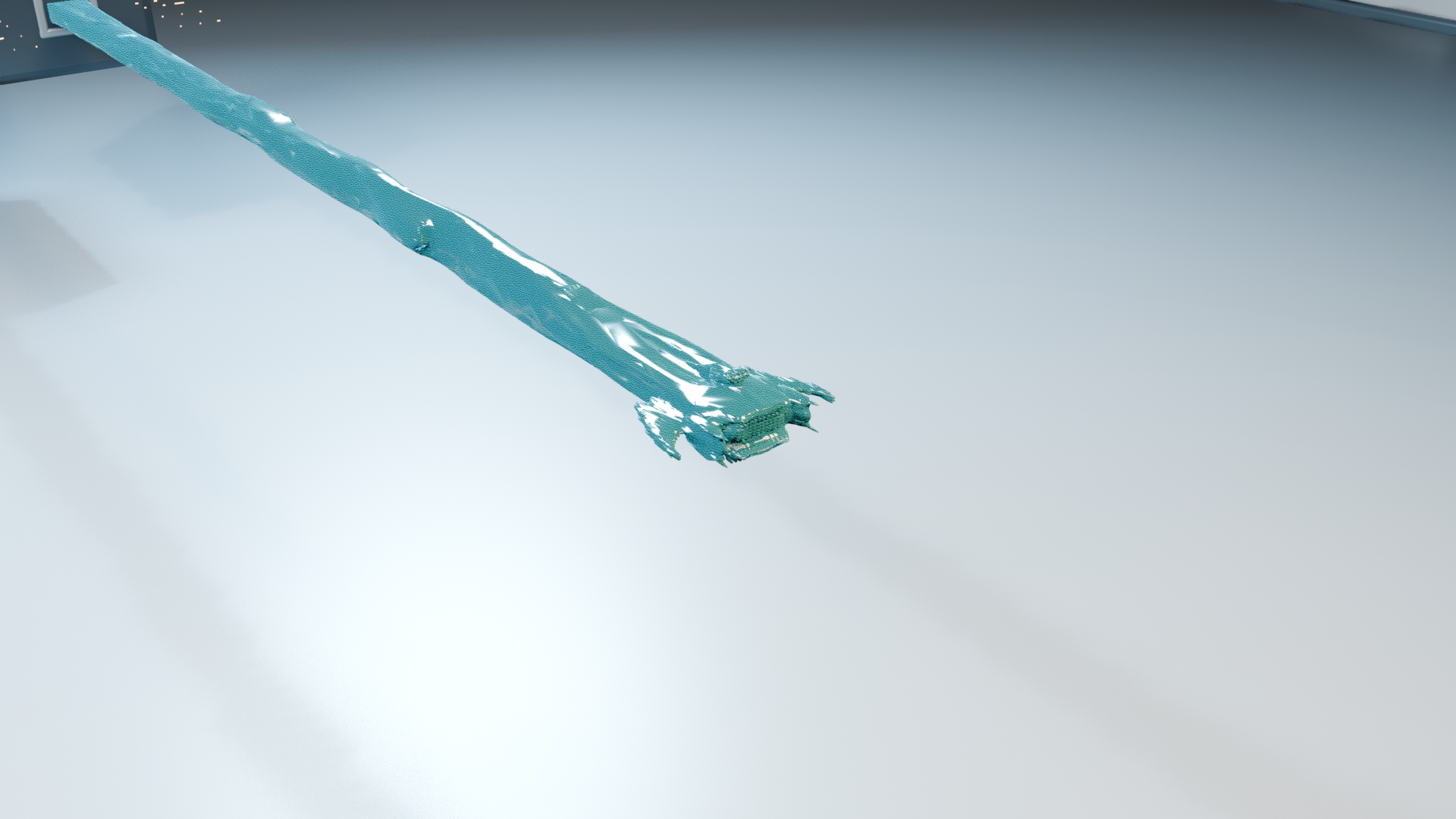
A frozen alpha.water=0.5 face mesh at the exact native 0.0055 s state. The camera path provides the motion while the displayed interface geometry remains the frozen native 0.0055 s state.
Side-oblique context for the rectangular slot, chamber, and connected interface surface.A closer view of the same frozen native state, retaining the face-based surface detail.
Topology and morphology diagnostics across all native states. The largest component retains a minimum face fraction of about 0.979.View the supporting axial and transverse sections
Axial phase and transverse mixture-velocity sections at native times 0.002, 0.006, and 0.012 s.
Related work
The case informs VisualOpenFOAM while remaining a separate scientific study.
Read-only native fields move through phase-aware checks, descriptive analysis, and deterministic figure or scene plans. Those requirements guide the adjacent CLI without changing the CFD case or its scientific interpretation.
Scientific basis
The 25 native states stay tied to liquid fraction, its derived gas complement, instantaneous mixture velocity, thresholds, units, and coordinate conventions.
Related software
This case supplies scientific context and representative field products for the adjacent Linux/headless workflow, including geometry, field semantics, units, and native times.
Read-only CFDnative fields and times
→
Phase-aware analysisphase, flow, cuts, morphology
→
Figures and morphologylabels, cuts, topology, media
→
Related software requirementsfor the separate CLI workflow
Visualization workflow
VisualOpenFOAM documents the separate case-inventory, VTK, field-report, and headless Blender planning path. Its reader implementation remains separate from the scientific results here.
Early-time laminar interface dynamics across 25 native states.
The 0.012 s computational window documents phase-aware fields, connected-interface morphology, and reproducible visualization within the selected laminar numerical configuration.